Curriculum
Personal Achievements.
Research Interests
I am currently
writing a PhD Thesis.
PC
Programs I wrote
for my PC.
RC Flight Simulator
Learn to fly your Radio
Control model airplane.
Spectrum
Published programs
I wrote for my Spectrum
Electronics
Electronic Circuits
I designed and built.
Electronics Page
In this page:
My First Circuits
Pre-Amplifiers
Audio Mixing Console
Power Suply
Wah-Wah Pedal
LCD Game
Strobe
TV Remote Control
Flapperon and Autolevel for RC Model
Aeroplane
| My First Circuits
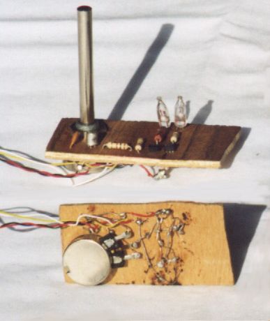
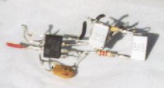
A long time ago, before I learned to make printed circuit boards I used to build my circuits on ply wood. The components inserted through holes and soldered one another on the other side. Insulating tape was used to prevent short circuits. It was just better than soldering the components in the air!
My funniest creation
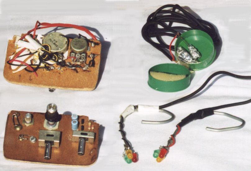
One of the options was 'Flashing Lights', which used a typical oscillator to switch on and off the LED's (the frequency was controlled with a variable resistor). Other option was 'Flash at Will', the LED's would flash once when a button (made with a clip and a pin) was pressed on the ply wood. This button would discharge a capacitor and allow the LED's to shine brightly during an instant and then fade away. But the most spectacular special effect was achieved when I included 'step sensors' which could light the LED's when I stepped on the floor. I only had to dance and the LED's would flash in synchronism with the music.
I had to wear the sensors at each of my ankles (held in place by the socks and a plastic band). When I stepped on the floor, a kitchen foil ball wrapped at the end of a spring would make contact with the bottom of the box where more kitchen foil was placed, making an effective shake sensor (the round green box in the picture). These were wired through my trousers to the control circuit. I had a lot of fun with it, although sometimes I got weird looks. |
| Pre-Amplifiers
My first operational amplifiers were used as audio preamplifiers. I boxed one of them for my acoustic guitar. Other preamplifiers, however, didn't enjoy the comfort of a wooden box, one of them didn't even had a PCB!
|
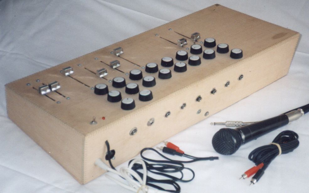
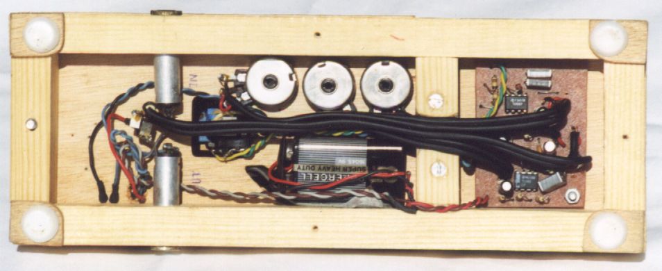
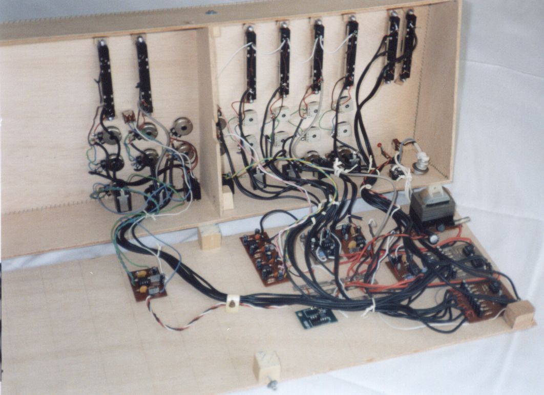
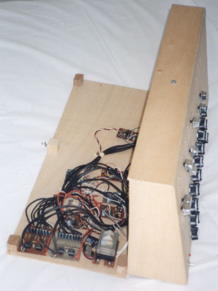
| Audio Mixing Console
I soon realised of the potential of Op. Amps. in audio. At the same
time I was into music, and needed to mix the microphone and the guitar
to feed it to my stereo. When designing the mixer, I realised that I could
easily add as many inputs as I needed, and I decided to build a basic mixing
console. It has four pre-amplified mono channels (e.g. for mics, guitars,
etc), two stereo channels (e.g. for tape input) and a special guitar input
with effects (distortion).
  |
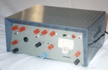
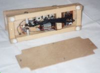
| Power Suply
I had the perfect box and the perfect transformer. There it was the opportunity to build a nice power supply. With -15,+15v and 5v outputs and non-regulated dc outputs for my home-made drill (the bit was soldered directly to the shaft of a motor (don't ask me about changing the bits)).
|
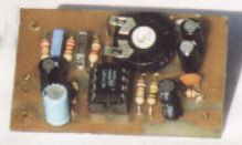
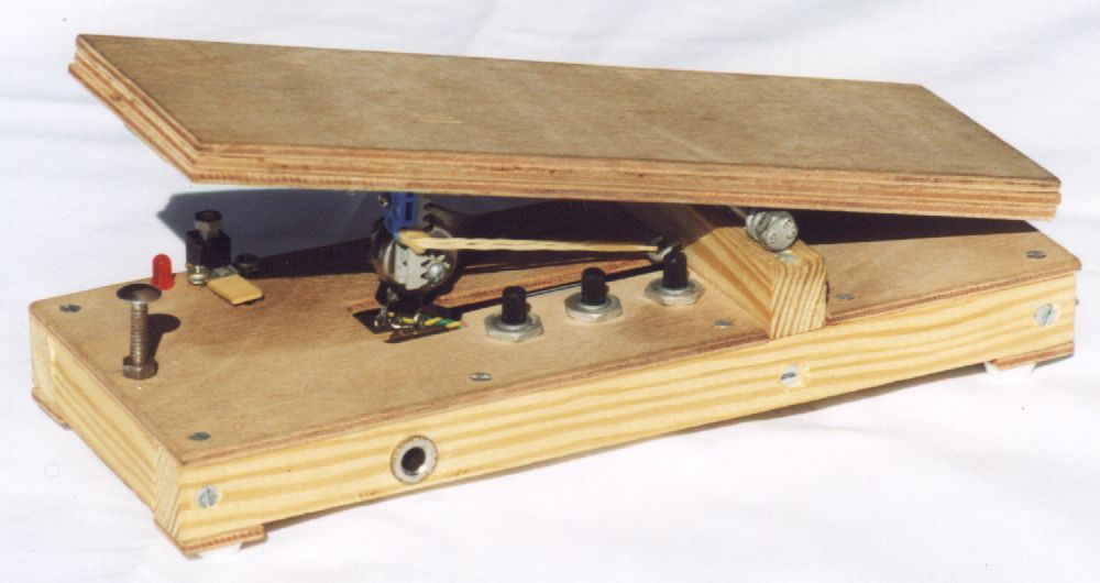
| Wah-Wah Pedal
The audio effect consists basically in amplifying a narrow frequency band. The centre of the amplified frequency band is selected with a potentiometer, and this pot is normally operated by foot. The highlighted frequencies and the the original signal are then mixed.
|
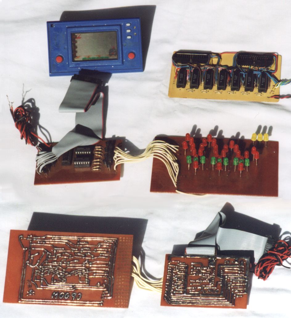
| LCD Game
In the original LCD game, the aim is to rescue as many men jumping from a burning building. Using two buttons, you control the position of the firemen, who hold a sort of trampoline, and must not miss any of the men who are endlessly jumping from the building. My first design used conventional digital IC's (latches, shift registers, buffers, counters... etc.). I tried this way despite the good advises I got, and soon I realised how impractical this design was.
After this first attempt, I decided to use a microprocessor/software implementation using my Spectrum. However, I still wanted to build some hardware, so I did a display with LED's which was connected to my Spectrum printer port. The 40 LED's were multiplexed in a 5x8 matrix, each LED would only be lit for 20% of the time. Hence a high refresh frequency was needed to avoid visible flashing so I wrote the whole program in assembly.
The flexibility of the software approach was definitely necessary for a successful design. After the sequencing, the logic and the algorithms had been developed, perhaps a wired version could have been feasible, just for the fun of creating a wired electronic monster! |
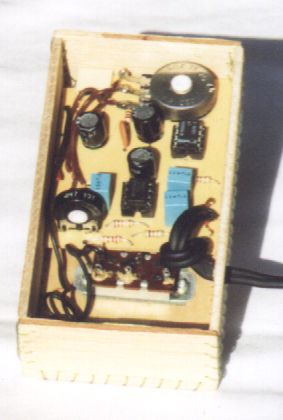
| Strobe
A strobe is a very bright light which flashes on and off very quickly. I used the bulb of a cheap camera flash and its transformer to generate the hundreds of volts needed to trigger the flash. I added a coarse (the knob in the picture) and a fine (the pot) frequency control. 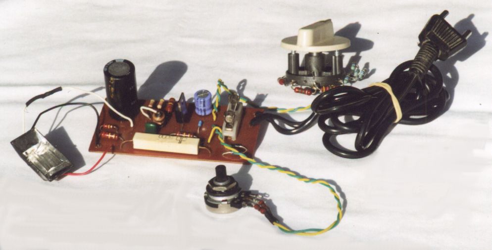 |
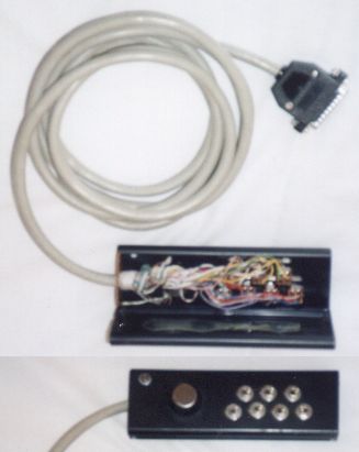
| TV Remote Control
I had a TV set without a remote control. I was really mad at so many adverts interrupting films without the chance to change nor the channel nor the volume (which broadcasters would put up for the ads and put back down for the film!). So I built my own 'Remote Control' by just wiring new switches with a long cable to the original switches in the TV set. The volume pot was wired as well (I had to set the TV pot at maximum volume and use the pot in the remote control in parallel).
|
| Flapperon and Autolevel for RC Model
Aeroplane
Last summer I designed a microcontroller based Flapperon and Autolevel circuit for my Radio Control Model Aeroplane. It is based on the PIC 16C84. I don't have pictures of the circuit, instead you can see my model (before I installed the ailerons though), but I have included the source code here.
Flapperon is the use of ailerons as flaps. If both ailerons are lowered, they effectively behave as faps, while retaining the normal operation of the ailerons. For use with a 4-channel radio gear, the flapperon is activated when the thrust control is below a preset position. The user can modify these three parameters:
- the speed of deflection, - and the amount of flapperon deflection. The Autolevel didn't quite work because it was impossible to discriminate between the ground and the sky since the ground was as bright as the sky. It would have worked if the ground was green grass, but since it was brown soil hit by the strong spanish sun, both ground and sky were equally bright.
|